British Pounds
How to Build A Peg Perego John Deere Ground Loader Tractor 12V Kids Ride On - Along with a Full Parts List & Instructions

Assembly Guide of How to Build A Peg Perego John Deere Ground Loader Tractor 12V Kids Ride On - Along with a Full Parts List & Instructions
If you've got a new Peg Perego John Deere Ground Loader 12V Tractor and you want some help building it, this blog post is the place to start!
As well as a full parts list for the Peg Perego John Deere Ground Loader at the bottom of this post along with images from the manual and photos of the key steps, we'll go into detail on every element of the assembly of your Ground Loader. If you have a second hand Ground Loader that you are restoring, then this page is also a great resource for you.
Use the parts list at the bottom of the post to identify any missing parts, then just click the links to order, or click here to get in touch with our friendly team of experts if you need more advice.
So, on with the main event - how exactly do you assemble a Peg Perego John Deere Ground Loader 12V? All you'll need to start is around 20 minutes and a Phillips Screwdriver.
Assembling your Kids Ride on Peg Perego Ground Loader 12V
Start by separating out the pieces and bags of smaller components, and make sure you have your manual handy. If you have mislaid your manual,scroll to the bottom of this page where you’ll find images of every page along with a full parts list. Put the sticker sheet to one side, as you won’t need this until the very end, and you don’t want to risk creasing it.
This guide follows the same steps as the manual, and we’ll include pictures from the manual along with explanations.
Before we begin, we recommend pre-charging your battery to ensure it remains in optimum condition. This first charge activates the battery, and it can damage the battery cell if this charge is cut short. Charge for a minimum of 8 hours, ideally 12 hours.
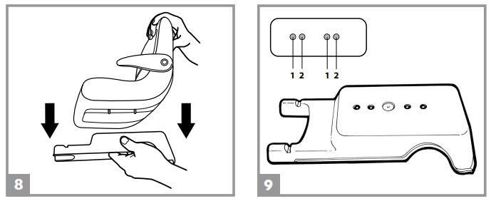
To assemble your John Deere Ground Loader 12V, begin by placing the green counterweight onto the front of the tractor chassis as shown below. Please note that the bushings on the chassis should pass through the holes in the counterweight. Ensure you fully slot the lower part of the counterweight onto the chassis and then secure with two screws as shown below::

Next it's time to install the hood of the vehicle. To do this, start by inserting the hinge into the seat of the chassis provided as shown in the image below, then screw down the hinge and close the hood, using a coin to lock the safety catch.
The headlights are next. There are four, two central and two outer. The central lights are identical, and can be installed on either of the two central light positions. The outer two are different, so make sure you line them up with the outer light slots to see which one is which. Press the light covers into position, ensuring you line up the three plastic latches on the rear of the light covers.

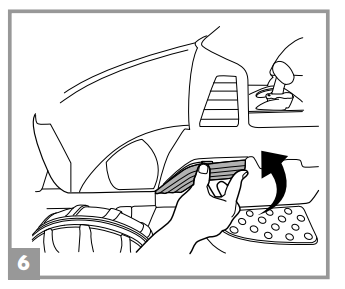
Next, we'll fit two small but important body parts, the side inserts, which fir onto the chassis as below:
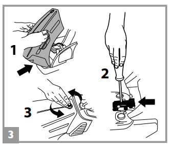
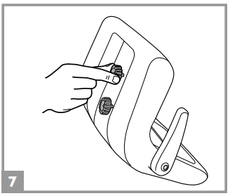
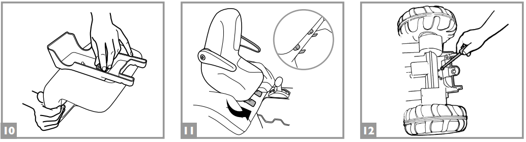
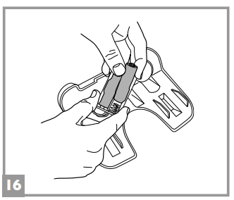
The seat is next. It's worth familiarising yourself with how the seat fits to the vehicle, as it is adjustable and can be moved forward or back into one of two positions depending on rider height. Start by undoing the knobs situated under the seat, then place the seat in line with the holes of the seat support as shown below:
To adjust the seat, fit it into one of the two sets of holes in the seat support, as shown below. Position 1 is for shorter riders, while position 2 will accommodate a taller child.
Once the seat is in place, screw the 2 locking knobs back on and ensure they are tight and that the seat and seat support are stable and firmly joined, then insert the front tabs of the seat supports into the corresponding slots on the chassis. Next it's time Reposition the seat support onto the tractor chassis and screw the 2 screws back on.
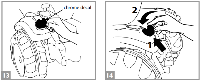
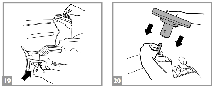
Next find your sticker sheet and locate the chrome rear reflector stickers. These fit on the back light position as shown in the image below, then fit the light covers, starting by inserting the bottom latches, then pressing in until the top latches catch.
Now install the two caps into the “C” points on the right and left back wheel arches as shown below:
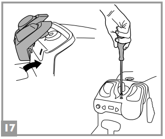
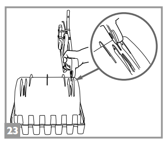
Once that's done, it's time to install the radio. Start by installing two AA 1.5V batteries into the radio, opening the rear cover (see figure below).
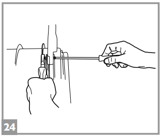
Once the batteries are fitted, put the radio in place by inserting the two clips into the chassis under the steering wheel shaft, fixing it with a screw as shown in the figure below:
Next, it's time to build and fit your steering wheel. Start by fitting the back and front parts of the steering wheel together, being careful not to bend or snap the plastic catches. Press the central steering wheel cap into place in the middle of the steering wheel.
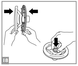
Now, push the steering wheel shaft up from under the tractor until it emerges from the top of the chassis and hold the shaft in this position and slide the steering wheel onto it.
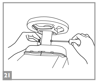
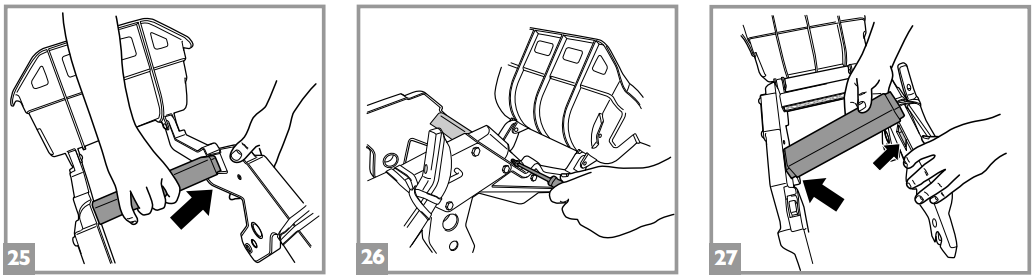
Next, fix the steering wheel with the bolt and nut provided, taking care to insert the bolt into the round hole and the nut into the hexagonal one, as shown below:
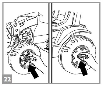
Now press the hubcaps onto the wheels; the larger ones go onto the front wheels, the smaller ones onto the rear wheels, as below:
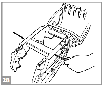
Your Ground Loader should be looking like a nearly complete tractor at this point, so now it's time to install the Ground Loader's key feature, its front digging arm. Start by overturning the bucket as shown below:
Now take note of the two digger arms. One has a handle, one does not. Remove the elastic on the loader arm with the lever, then insert the arm spring into the corresponding point on the bucket. Slide a washer onto the screw and insert it into the corresponding holes to connect the bucket to the loader arm. Now slide a second washer onto the screw, then insert the nut. Tighten with a screwdriver and pliers. Repeat on the opposite side. See the image below for detail:
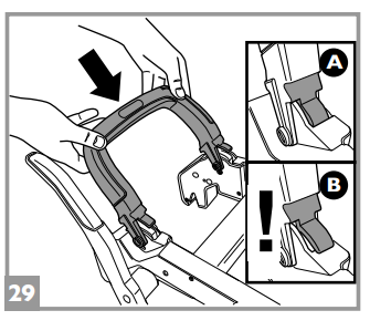
Next, install one of the two cross pieces onto the front part of the loader arms, as shown in the figure below, and fix with the two screws provided (one for each side). Now insert the second cross piece onto the rear part of the loader arms, and fix with the two screws provided (one for each side), as shown below:
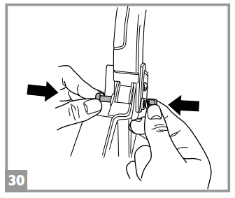
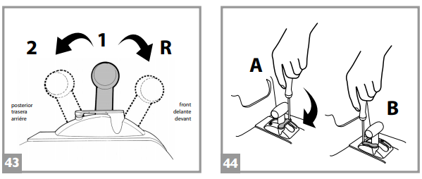
The handle now needs to be fitted. Put the handle in place as shown in the diagram below. Note that the picture in box A shows the CORRECT position of the lower tab, which should be inserted into the slot of the loader arm; the picture in box B shows the INCORRECT position.
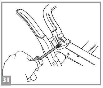
Once things are in the correct postions, insert a nut into the hexagonal hole on the inner part of the handle. Insert a screw onto the opposite side, then fix the handle into place by tightening the screws. Repeat on the opposite side.
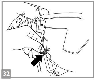
Now the bucket is assembled, it needs to be tensioned so that the lever will move it. To do this, insert a stud into the cavity on the right side of the bucket, lining up the respective holes as below:
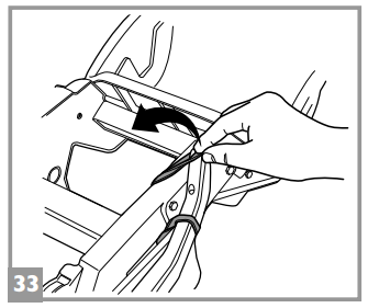
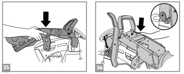
Now remove the elastic tying the metal tension rod to the lever, place the control lever in a vertical position, and, pressing hard, attach the tension rod to the bucket. Now the loader can be fitted to the main tractor body. Start with the rear part of the loader, as shown in the diagram below, then push down, ensuring that the mounting points align as shown in the zoomed in circle in step 36 below:
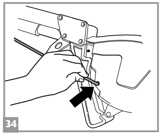
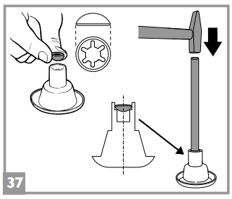
The next step can be a little tricky, so take your time and study the images below carefully. Start by inserting a large washer into the conical washer bearing as shown in the picture. Next, put the long iron pin into place, and with the help of a hammer, insert it all the way into the washer.
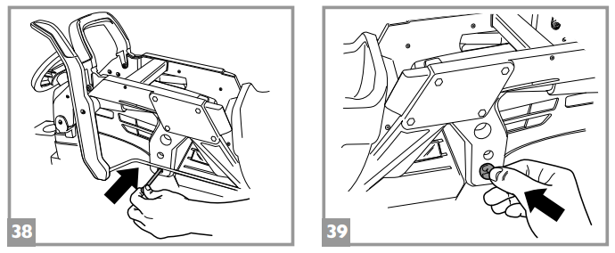
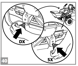
The next step is to line up the loader holes with those of the cab and insert the pin, placing a stud on the opposite side of the pin. No tools are required for this step. Complete the attachment of the pin using the two washer bearings provided, pressing the two parts hard and simultaneously.
Once this is completed, it’s time to place the stickers on the body. If you tear any of your stickers, or would like some extra ones, we sell full Ground Loader sticker sheets at this link.
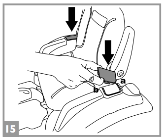
The final step is to take your charged battery and install it. To do this, lift the hood as shown in the image below, and then connect the battery's cable to the matching connector in the vehicle. Slide the battery int its bay, and close the hood, and you are now ready to dig and drive as only a Ground Loader can.
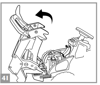
This completes the construction of your Kids Ride on John Deere Ground Loader, and now all you need to do is charge your battery and connect it to the vehicle. The first battery charge is a very important step, as it conditions the battery cell, ensuring you get maximum battery life and drivetime. We recommend a 12 hour initial charge with no interruption. Once this is done, simplt slide the battery into the battery bay in the front of the vehicle, and connect the cable to the matching connector inside the battery compartment. Finally, close the compartment and screw it shut.
If you need any further help with assembling your Ground Loader, don’t hesitate to get in touch with our friendly team, who will be happy to help. If your Ground Loader is a second hand item, we are happy to help, both with guidance and in supplying any missing or worn parts. We stock all parts for the Peg Perego John Deere Ground Loader12V, and you can click here to see them all. If you can't find the part on our site, just click here to get in touch and we'll be happy to assist.
Instructions for using your Peg Perego John Deere Ground Loader 12V
• GEAR SHIFT LEVER: The vehicle has three speeds. ATTENTION: when it is removed from the packaging, the vehicle only travels in first gear and in reverse. To use 2nd gear, see figure 44 below, and follow these steps:
1. Remove the screw in the second gear lock
2. Turn the lock to the next position
3. Screw the lock back on. All gears are now available.
• ACCELERATOR PEDAL/ELECTRIC BRAKE: The
brake will automatically be applied when the foot
is lifted off the pedal.
• FM RADIO: To switch on, off and adjust the
volume turn knob A. To select the radio stations
press the two triangular buttons (see figure).
• LOADER: To lower the loader, push the handle forward as far as it will go. To raise the loader, pull back the handle and lock into place.
To turn the bucket forward, pull back the side lever. Release the lever to return the bucket to the starting position.
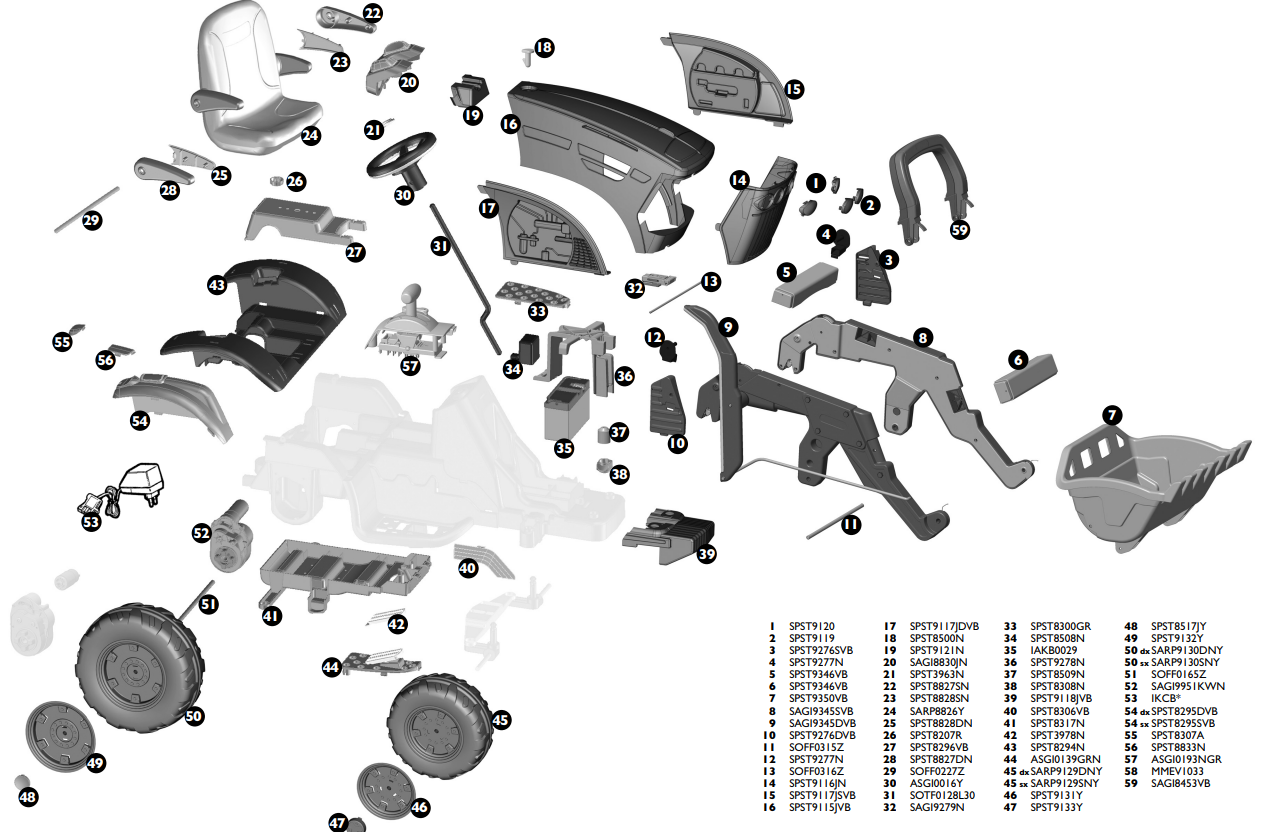
12v Ride on John Deere Ground Loader Complete Parts List:
The diagram below shows all the 12v Ground Loader parts - to find the part ID, just use the table below the diagram.